Category Archives: CCD Cameras
QuickCam and the Apple II, Part II
Part II – The Software
The software turns out to be a bit easier once all the hardware is built. The two main routines required are the read and write routines. Writing a data byte to the QC involves writing the data to the output port then reading back the echo of the data from the QC to ensure it was received. Reading a data byte from QC involves bringing PCAck (Strobe) high, waiting for the QC to respond with CamRDY high, then reading the first nybble on the input data port. Once the nybble has been read, deassert PCAck (Strobe), wait for CamRDY to go low, then read the second nybble from the input data port. Because of the way the PC parallel port works, Nybble3 from the QC went through an inverter so the QC actually compliments Nybble3 so the PC would read the correct value right from the I/O port. However, the APIC isn’t mapped like the PC parallel port, so this bit will show up inverted on the input data port. The 6502 has to compliment Nybble3 to get the correct value. One other issue mentioned in the hardware post has to be dealt with – the Output Strobe. On the APIC, the Output Strobe connected to PCAck, has an automatic pulse duration that can be set with switches on the card. Because the actual duration of this pulse is dynamic, handshaking with the CamRDY signal, a way to keep re-triggering this signal so it doesn’t prematurely deactivate has to be developed. As luck would have it, the maximum strobe pulse is 15 us, just long enough to check the status of PCAck and either re-trigger the strobe or read the data on the input port before the strobe de-asserts. Finally, reading the echo from a data write is the exact same code as reading a data byte, the two are combined and the data write routine falls right into the data read. Here are the two most important routines with the slot*16 in the X register:
QCWRITE STA $C080,X  ; DATA OUT -> CMD
QCREAD  STA $C082,X  ; STROBE -> PCACK
        LSR $C084,X  ; ACK (BIT 0) <- CAMRDY
        BCC QCREAD
        LDA $C083,X  ; DATA IN <- HI NYBBLE
        AND #$F0     ; DO ENOUGH WORK SO HANDSHAKE CAN BE SKIPPED
        EOR #$88     ; COMPLIMENT NYBBLE3
        STA TMP
        LDA #$0F
        AND $C083,X  ; DATA IN <- LO NYBBLE
        EOR TMP      ; COMBINE LO AND HI NYBBLES
        RTS
This is the core of the code to read and write the QC. The other important routine is the reset/init routine. The original B/W QC would return a parameter to the GetVersion command of 0. The later Color QC returned a non-zero value, plus an additional value. Care must be taken to take this into account if code is to work on both. Also, this code isn’t smart – if a QC isn’t attached, it will wait forever.
RESET   LDA #$FF
        STA $C085,X ; RESET QC
        JSR $FCA8   ; WAIT
        LDA #$17    ; GET_VER
        JSR QCWRITE
        CMP #$17    ; GOOD ECHO?
        BNE QCERR
        JSR QCREAD
        BEQ QCBW
        PHA
        JSR QCREAD ; COLOR QC HAS 2 PARMS
        PLA
QCBW    RTS
Once we can initialize the QC and read and write commands, time to read video frame data. The QC can return pixel data in either 4BPP or 6BPP mode. Due to the limitations of the Apple II graphics, 4BPP seems adequate so I don’t bother with 6BPP. I wrote a very simple program to grab small video frames and put them on the Apple’s low resolution graphics screen. By mapping the color blocks into a corresponding grey scale ramp and displaying the result on a monochrome monitor, live video that roughly resembles what the QC is looking at results. I added controls to adjust the exposure value and contrast to that the best image can be obtained given the severe constraints of 4 bit pixels and a 40×48 graphics mode. Finally, I added a high resolution capture command that would take a video frame and display it on the high res screen. Now the high res screen only shows 1 bit pixels, so I had to employ a primitive error diffusion algorithm to get a respectable image. I’ll let you be the judge of the results:
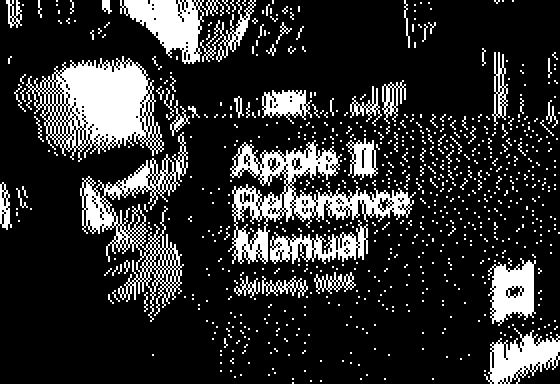
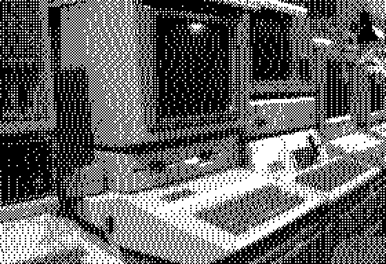
I added a small ordered dither to the pixel calculations to bring out the mid and low grey values. Here is an image of some of my collection:
Finally, here is the code for the lo-res video/hi-res frame capture. It isn’t really well documented, but is fairly short and simple. Meant to be assembled by EDASM.
        ORG     $2000
DATAOUT EQU     $C080
STROBE  EQU     $C082
DATAIN  EQU     $C083
ACK     EQU     $C084
RESET   EQU     $C085
WAIT    EQU     $FCA8
ERR     EQU     $03
TMP     EQU     $06
HPIX    EQU     $06
LASTERR EQU     $07
*
* HARD-CODE SLOT 1 AND RESET
*
        LDX     #$10
        JSR     QCRESET
        BCC     GR
        RTS
*
* SET LORES GRAPHICS
*
GR      LDA     $C050
        LDA     $C056
        LDA     $C052
        LDA     $C054
*
* SET FRAME DIMENSIONS
*
        LDX     #$10
        LDA     #45
        JSR     QCLEFT
        LDA     #25
        JSR     QCTOP
        LDA     #20
        JSR     QCNUMH
        LDA     #48
        JSR     QCNUMV
*
* SET FRAME CONTRAST/EXPOSURE
*
SETCONT LDA     CONT
        JSR     QCCONT
SETEXP  LDA     EXP
        JSR     QCEXP
*
* GRAB FRAME INTO LORES GRAPHICS SCREEN
*
VIDEO   LDA     #$08
        JSR     QCFRAME
        LDA     #$00
        STA     LINE
*
* EVEN LINES
*
ELINE   JSR     $F847   ; GBASECALC
        LDY     #$00
EPIX    STA     STROBE,X
        LSR     ACK,X
        BCC     EPIX
        LDA     DATAIN,X
        AND     #$0F
        TAX
        LDA     GREYLO,X
        LDX     #$10
        STA     ($26),Y
        INY
        LDA     DATAIN,X
        AND     #$0F
        TAX
        LDA     GREYLO,X
        LDX     #$10
        STA     ($26),Y
        INY
        CPY     #40
        BNE     EPIX
*
* ODD LINES
*
OLINE   LDY     #$00
OPIX    STA     STROBE,X
        LSR     ACK,X
        BCC     OPIX
        LDA     DATAIN,X
        AND     #$0F
        TAX
        LDA     GREYHI,X
        LDX     #$10
        ORA     ($26),Y
        STA     ($26),Y
        INY
        LDA     DATAIN,X
        AND     #$0F
        TAX
        LDA     GREYHI,X
        LDX     #$10
        ORA     ($26),Y
        STA     ($26),Y
        INY
        CPY     #40
        BNE     OPIX
        INC     LINE
        LDA     LINE
        CMP     #24
        BEQ     EOFRM
        JMP     ELINE
EOFRM   JSR     QCEOF
*
* CHEK FOR KEYPRESS
*
        LDA     $C000
        BMI     KEYPRESS
        JMP     VIDEO
KEYPRESS STA    $C010
        CMP     #$D1    ; Q
        BEQ     DONE
        CMP     #$AB    ; +
        BNE     KP1
        INC     EXP
        JMP     SETEXP
KP1     CMP     #$AD    ; -
        BNE     KP2
        DEC     EXP
        JMP     SETEXP
KP2     CMP     #$BC    ; <
        BNE     KP3
        DEC     CONT
        JMP     SETCONT
KP3     CMP     #$BE    ; >
        BNE     KPEND
        INC     CONT
        JMP     SETCONT
KPEND   CMP     #$A0    ; SPACEBAR
        BEQ     HRCAP
        JMP     VIDEO
DONE    JMP     $FB39   ; TEXT
*
* HIRES FRAME CAPTURE
*
HRCAP   LDA     $C057
        LDA     $C055
        LDA     #20
        JSR     QCLEFT
        LDA     #25
        JSR     QCTOP
        LDA     #140
        JSR     QCNUMH
        LDA     #192
        JSR     QCNUMV
        LDA     #$00
        JSR     QCFRAME
        LDA     #$40
        STA     $E6
        STA     $27
        LDY     #$00
        STY     $26
        STY     LINE
        STY     LASTERR
*
* FIRST SEVEN BITS OF HIRES WORD - EVEN LINES
*
EHLINE  JSR     QCPIXHI
        CLC
        ADC     #4
        JSR     PIXTST
        JSR     QCPIXLO
        SEC
        SBC     #1
        JSR     PIXTST
        JSR     QCPIXHI
        CLC
        ADC     #4
        JSR     PIXTST
        JSR     QCPIXLO
        SEC
        SBC     #1
        JSR     PIXTST
        JSR     QCPIXHI
        CLC
        ADC     #4
        JSR     PIXTST
        JSR     QCPIXLO
        SEC
        SBC     #1
        JSR     PIXTST
        JSR     QCPIXHI
        CLC
        ADC     #4
        JSR     PIXTST
        LDA     HPIX
        LSR
        STA     ($26),Y
        INY
*
* SECOND BYTE OF HIRES WORD
*
        JSR     QCPIXLO
        SEC
        SBC     #1
        JSR     PIXTST
        JSR     QCPIXHI
        CLC
        ADC     #4
        JSR     PIXTST
        JSR     QCPIXLO
        SEC
        SBC     #1
        JSR     PIXTST
        JSR     QCPIXHI
        CLC
        ADC     #4
        JSR     PIXTST
        JSR     QCPIXLO
        SEC
        SBC     #1
        JSR     PIXTST
        JSR     QCPIXHI
        CLC
        ADC     #4
        JSR     PIXTST
        JSR     QCPIXLO
        SEC
        SBC     #1
        JSR     PIXTST
        LDA     HPIX
        LSR
        STA     ($26),Y
        INY
        CPY     #40
        BEQ     NEXTEHLINE
        JMP     EHLINE
NEXTEHLINE JSR  $F504   ; INC HPOSN
        INC     LINE
        LDY     #$00
*
* FIRST SEVEN BITS OF HIRES WORD - ODD LINES
*
OHLINE  JSR     QCPIXHI
        SEC
        SBC     #4
        JSR     PIXTST
        JSR     QCPIXLO
        CLC
        ADC     #1
        JSR     PIXTST
        JSR     QCPIXHI
        SEC
        SBC     #4
        JSR     PIXTST
        JSR     QCPIXLO
        CLC
        ADC     #1
        JSR     PIXTST
        JSR     QCPIXHI
        SEC
        SBC     #4
        JSR     PIXTST
        JSR     QCPIXLO
        CLC
        ADC     #1
        JSR     PIXTST
        JSR     QCPIXHI
        SEC
        SBC     #4
        JSR     PIXTST
        LDA     HPIX
        LSR
        STA     ($26),Y
        INY
*
* SECOND BYTE OF HIRES WORD
*
        JSR     QCPIXLO
        CLC
        ADC     #1
        JSR     PIXTST
        JSR     QCPIXHI
        SEC
        SBC     #4
        JSR     PIXTST
        JSR     QCPIXLO
        CLC
        ADC     #1
        JSR     PIXTST
        JSR     QCPIXHI
        SEC
        SBC     #4
        JSR     PIXTST
        JSR     QCPIXLO
        CLC
        ADC     #1
        JSR     PIXTST
        JSR     QCPIXHI
        SEC
        SBC     #4
        JSR     PIXTST
        JSR     QCPIXLO
        CLC
        ADC     #1
        JSR     PIXTST
        LDA     HPIX
        LSR
        STA     ($26),Y
        INY
        CPY     #40
        BEQ     NEXTOHLINE
        JMP     OHLINE
NEXTOHLINE JSR  $F504   ; INC HPOSN
        INC     LINE
        LDA     LINE
        CMP     #192
        BEQ     EXIT
        LDY     #$00
        JMP     EHLINE
EXIT    JMP     QCEOF
*
* SIMPLE ERROR DIFFUSION
*
PIXTST  CLC
        ADC     LASTERR
        CMP     #$08
        BMI     PIXNEG
        ROR     HPIX
        SEC
        SBC     #$0F
        CMP     #$80
        ROR
        STA     LASTERR
        RTS
PIXNEG  LSR     HPIX
        CMP     #$80
        ROR
        STA     LASTERR
        RTS
EXP     DB      96
CONT    DB      104
LINE    DB      $00
*
* QCAM PIXEL DATA -> LORES GREYSCALE
*
GREYHI  DB      $30,$60,$A0,$50,$40,$80,$20,$10
        DB      $00,$F0,$E0,$D0,$70,$B0,$90,$C0
GREYLO  DB      $03,$06,$0A,$05,$04,$08,$02,$01
        DB      $00,$0F,$0E,$0D,$07,$0B,$09,$0C
***************************
*
*    QUICKCAM ROUTINES
*
***************************
*
* RESET QUICKCAM
*
QCRESET STA     RESET,X
        STX     TMP
        LDA     #$FF
        JSR     WAIT
        LDX     TMP
        LDA     #$17    ; GET VERSION
        JSR     QCWRITE
        CMP     #$17
        BEQ     QCOK
        SEC
        RTS
QCOK    JSR     QCREAD
        BEQ     QCBW
        PHA
        JSR     QCREAD
        PLA
QCBW    LDA     #$19    ; SET CONTRAST
        JSR     QCWRITE
        LDA     #104
        JSR     QCWRITE
        LDA     #$1B    ; AUTO CALIBRATE
        JSR     QCWRITE
        JSR     QCWRITE ; DUMMY PARAMETER
QCCAL   LDA     #$7F
        JSR     WAIT
        LDA     #$21    ; GET OFFSET
        JSR     QCWRITE
        JSR     QCREAD
        CMP     #$FF
        BEQ     QCCAL
        CLC
        RTS
*
* SET CONTRAST IN ACCUM
*
QCCONT  PHA
        LDA     #$19    ; SET CONTRAST
        JSR     QCWRITE
        PLA
        JMP     QCWRITE
*
* SET EXPOSURE IN ACCUM
*
QCEXP   PHA
        LDA     #$0B    ; SET EXPOSURE
        JSR     QCWRITE
        PLA
        JMP     QCWRITE
*
* SET TOP OF FRAME
*
QCTOP   PHA
        LDA     #$0D
        JSR     QCWRITE
        PLA
        JMP     QCWRITE
*
* SET FRAME LEFT COORDINATE
*
QCLEFT  PHA
        LDA     #$0F
        JSR     QCWRITE
        PLA
        JMP     QCWRITE
*
* SET FRAME LINES TO TRANSFER
*
QCNUMV PHA
        LDA     #$11
        JSR     QCWRITE
        PLA
        JMP     QCWRITE
*
* SET FRAME PIXELS PER LINE
*
QCNUMH  PHA
        LDA     #$13
        JSR     QCWRITE
        PLA
        JMP     QCWRITE
*
* COMPLETE END OF FRAME
*
QCEOF   STA     STROBE,X
        RTS
*
* SEND VIDEO FRAME
*
QCFRAME PHA
        LDA     #$07
        JSR     QCWRITE
        PLA
*
* WRITE BYTE TO CAM, FALL THRU TO READ ECHO
*
QCWRITE STA     DATAOUT,X
*
* READ BYTE FROM CAM
*
QCREAD  STA     STROBE,X
        LSR     ACK,X
        BCC     QCREAD
        LDA     DATAIN,X
        AND     #$F0
        EOR     #$88
        STA     TMP
        LDA     #$0F
        AND     DATAIN,X
        EOR     TMP
        RTS
*
* READ HI NYBBLE FROM CAM
* - NYBBLE IS DUPLICATED IN HI & LO NYBBLE
*
QCREADHI STA    STROBE,X
        LSR     ACK,X
        BCC     QCREADHI
*
* READ LO NYBBLE FROM CAM
* - SAME AS HI NYBBLE W/O WAIT
*
QCREADLO LDA    DATAIN,X
        EOR     #$88
        RTS
*
* READ 4BPP AS B/W RAMP 0->F
*
QCPIXHI STA     STROBE,X
        LSR     ACK,X
        BCC     QCPIXHI
QCPIXLO LDA     DATAIN,X
        EOR     #$07
        CLC
        ADC     #$01
        AND     #$0F
        RTS
QuickCam and the Apple II
Part I – The Hardware
I finally got around to looking into connecting an old Connectix Greyscale QuickCam (QC) to an Apple II by way of the Apple Parallel Interface Card (APIC). I had a couple of QuickCams lying around from my webcam astronomy days and bought some APICs off the ePay in anticipation of hooking them together someday. I chose the APIC because it was the only parallel interface card I could find that implemented a full 8-bit input port.
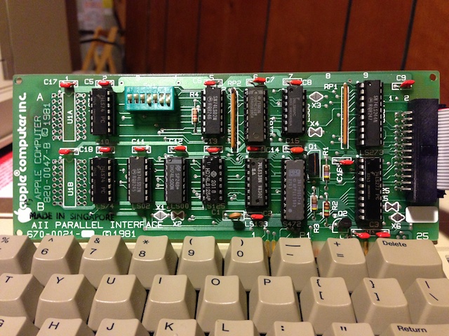
Someday finally came. I pulled out the programming specs on the QC and the APIC Installation and Operation Manual and went about figuring out the details of mapping the PC parallel port pinouts of the QC to the APIC. This is the cable magic required to connect them together:
APIC Signal/Pin        QuickCam Signal/Pin
Strobe    15           PCAck     17
Ack       16           CamRDY    15
Input D7  18           Nybble3   11
Input D6  21           Nybble2   10
Input D5  19           Nybble1   12
Input D4  14           Nybble0   13
Input D3  25           Nybble3   11
Input D2   3           Nybble2   10
Input D1  17           Nybble1   12
Input D0   1           Nybble0   13
Output D7 13           Cmd7       9
Output D6 12           Cmd6       8
Output D5 11           Cmd5       7
Output D4 23           Cmd4       6
Output D3 22           Cmd3       5
Output D2  8           Cmd2       4
Output D1  6           Cmd1       3
Output D0  5           Cmd0       2
Aux Strobe 7           *Reset    16
GND       24,20,4,2    GND       18-25
There are a few things to take note of. First, the output from the QC, Nybble3-0 is mapped to both to the most significant and the least significant nybble of the APICs 8 bit input port. Since there are only enough I/O pins to implement the 4 bit communications protocol, I decided to map the one QC nybble to a full byte of input to the APIC. The 6502 isn’t very good at shifting, so this alleviates the need to shift the nybble around for certain algorithms. The second thing to note is the output strobe of the APIC connected to the PCAck of the QC. This is one of the major handshake lines that works in conjunction with the CamRDY line for transferring data. The host needs to hold this line high until the QC signals data is ready by raising CamRDY. However, the APICs strobe is pulsed for a short duration, automatically returning to its previous state based upon switch settings on the APIC. The strobe duration can be set using the first three switches on the APIC, from 1 us to 15 us. Luckily, by maxing out the strobe duration to 15 us gives the 6502 just enough time to check the PCAck from the QC and re-triggering the strobe if it isn’t ready, or reading the data input port if it is – all before the strobe falls. The second nybble from the QC quickly follows the first, so there was no need to check the handshaking signals again if the 6502 did enough work in-between nybble reads. The last fortuitous connection was the Aux Strobe to *Reset. The Aux Strobe isn’t really documented in the APIC manual except for the block diagram. It delivers a short pulse whenever a certain address is accessed, and just happens to be active low, matching the requirements for the *Reset on the QC. The APIC allows for the selection of active high or low for the regular strobe signal, thus matching the QCs PCAck signal. The switch settings required on the APIC are thus:
      APIC SWITCH BLOCK
 1   2   3   4   5   6   7
ON  ON  ON  OFF ON  OFF OFF
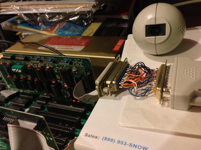
As this is a fairly delicate connection that I didn’t want to have to re-solder, I wanted to get a DB-25 dual ended hood to create a professional, reliable dongle. However, those parts are no longer made, so I had to buy two DB-25 hoods and take a hack saw to them to create the piece I wanted. Ultimately, I ended up with this:
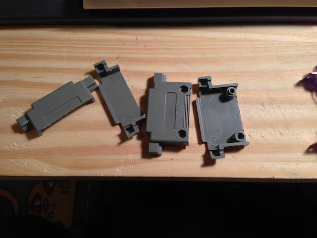
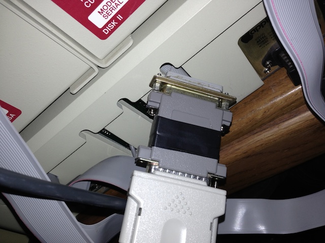
Finally, the QuickCam takes its power from the PS/2->AT keyboard connector since the parallel port doesn’t provide any. I went through the parts bin, found an old +5V power adapter, an old keyboard cable to hack up, and along with a trip to Radio Shack for the power plug, created this:
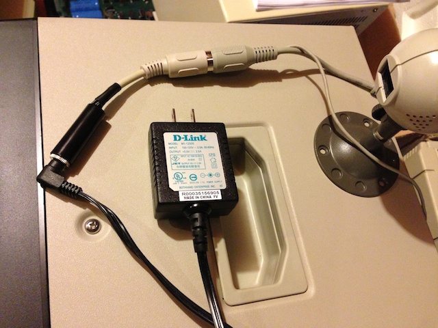 The only lines required to connect are the +5V and ground. Here is a link to a nice diagram showing which pins are power for the two connector types: http://www.bbdsoft.com/keyboard.html
Continue on to Connectix QuickCam and the Apple II, Part II – The Software