Doing Something Useful
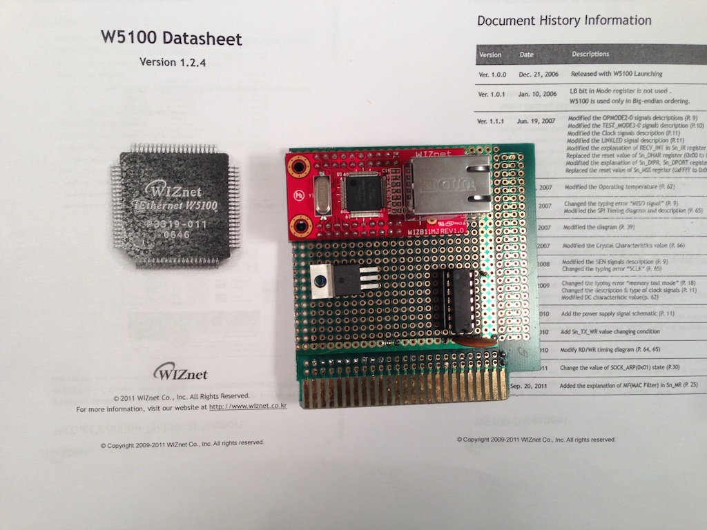
After building the basic framework for interfacing the Apple II to an Arduino over the game port, something useful had to be created with it. I had an Ethernet Shield lying around that also happens to have an SD card slot.
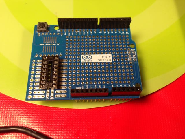
Arduino with Ethernet and Proto Shields
There are already plenty of Ethernet products available for the Apple II, but few SD card options for transferring individual files. FloppyEmu, from Big-Mess-O-Wires is a great product and I highly recommend it, but for my project I wanted something closer to a hardware version of CiderPress: the Apple disk image utility.
I’ve worked on a similar project with Rodney Ross to bring the Apple II Pi’s virtual disk interface to the Super Serial Card using an Atmel processor and the SdFat library. I thought I would take the same basic framework but create a different use: interact directly with the FAT filesystem on the SD card by way of the SdFat library. This wouldn’t be a virtual drive (that would be easy enough to implement), but a direct interface to the FAT filesystem on an SD card. Also, many new laptops come with an SD card reader built in, so it makes for a great way to sneaker-net files back and forth. Both individual files and floppy disk image files can be read and written to Apple connected storage. ProDOS hard disks, CFFAs, and such can copy files using the CiderPress file naming convention to retain the ProDOS meta information. Floppy disk images can be read and written directly to physical floppy drives. The challenge is to make the data transfer over the game port fast enough to support copying large files back and forth. Sound good? Want to build one yourself? Read on…
The Hardware
One of the goals when creating this project was to use easy-to-obtain parts so that anyone with a little time could replicate the hardware and software themselves. The parts list is nice and short:
- 1 Arduino Uno
- 1 Logger Shield or Ethernet Shield + Proto Shield
- 16 wire Ribbon Cable
- 2 IDC 16 pin DIP Plugs (for both ends of the ribbon cable)
- 1 16 pin DIP Socket
- 6 Wires
- Optional – 1 SPDT PCB Slide Switch (II & IIGS functionality)
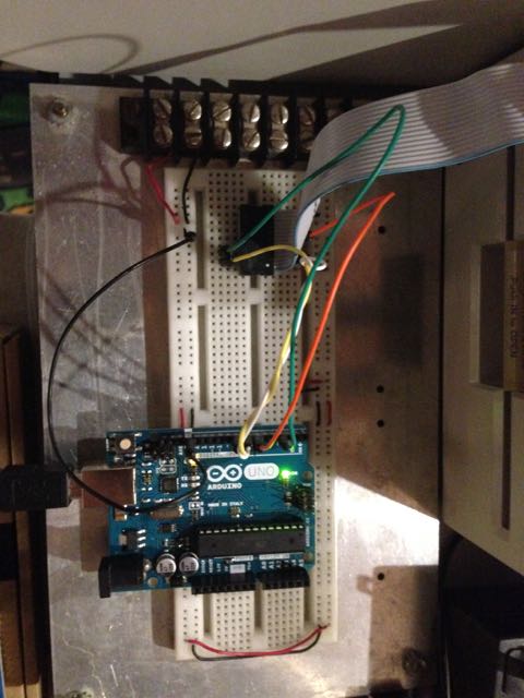
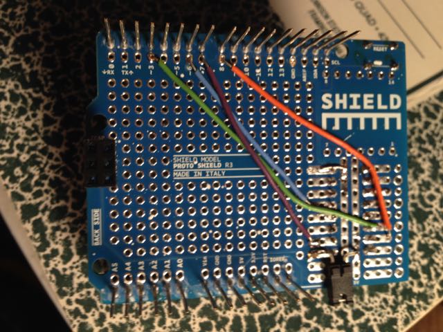
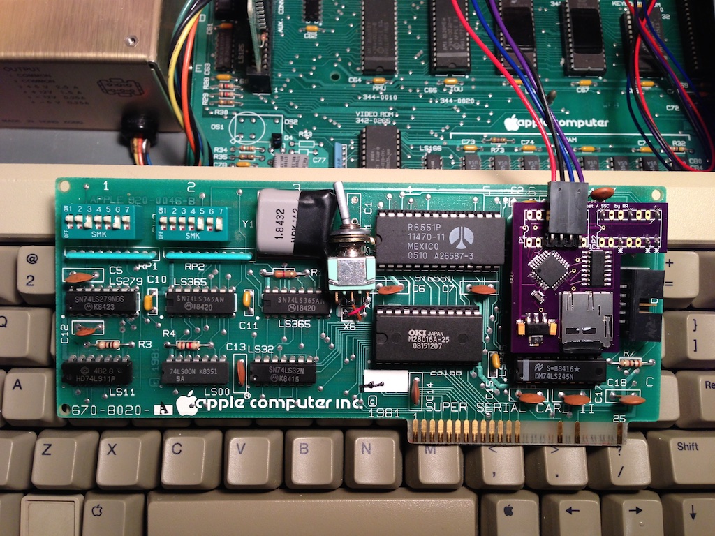
Along with a soldering iron and some solder, you will be good to go. You can see my build using the Proto Shield on my previous post. One modification I made was for the Apple IIgs, which lacks the $C040 Strobe signal, was to connect the AN2 pin as the SCLK signal. I used the slide switch to select between the $C040 Strobe and AN2 going to the Arduino’s Digital Pin 6. Using AN2 for the SCLK is slower than the $C040 Strobe, but the only option on the IIgs. Here is the pin connections I use:
 Apple II        Signal         Arduino
 --------        ------         -------
   AN0            MOSI        Digital Pin 8
   AN1             SS         Digital Pin 3
   PB0            MISO        Digital Pin 7

Apple II/IIe     Signal         Arduino
------------     ------         -------
 C040 Strobe      SCK         Digital Pin 6

Apple IIgs       Signal         Arduino
----------       ------         -------
    AN2           SCK         Digital Pin 6
Apple II game port diagram is available from:
http://www.1000bit.it/support/manuali/apple/R023PINOUTS.TXT
Arduino Uno pin diagram is available from:
http://www.gammon.com.au/forum/?id=11473
The Firmware
Once the hardware is connected (built seems a little extreme), the software to give the Arduino its purpose needs to be programmed. Three items need to be installed on your computer (modern, not retro):
The Arduino IDE will create a working directory for your projects. Inside this directory, you should create a sub-directory called AppleSlave and place the AppleSlave.ino file there. From the SdFat download, move the SdFat/SdFat/ directory into the libraries/ directory in your working Arduino directory. You should be able to load the AppleSlave.ino project into the Arduino IDE and build it, bringing in the SdFat library. Depending on which Arduino shield you are using for the SD card interface, you may need to edit the AppleSlave source. Near the top, you will find a line that looks like:
const int sdSSpin = 4;
This is the default when using the Ethernet Shield. If you have the Logger Shield, this line should be changed to use 10 instead of 4. If all is in the proper location, you should be able to plug the Arduino into the computer with a USB cable, and build/upload.
The current firmware is still a work in process. There are a few more functions to implement, but it is enough to support the software below.
The Software
There are currently five basic utilities to interact with the files on an SD card.
- FATCAT – display catalog of SD card
- FATGET – get a file from the SD card
- FATPUT – put a file onto the SD card
- FATWRITEDSK – write an image on the SD card to floppy
- FATREADDSK – read a floppy to an image on the SD card
These programs are written in PLASMA, a mid-level programming language developed for writing new applications using modern syntax and efficient execution. You can download a disk image, SDFAT.PO, containing a bootable ProDOS floppy with these programs on it, ready to go. Now you have a chicken and egg problem: getting the image written to an actual floppy will require a program like ADTPro (or maybe a friend can create a floppy for you).
Using A2SdFat
Using the utilities involves the PLASMA command line interface. It is a very simplified environment, but not hard to use. You can get a ProDOS catalog by entering ‘C’ and return. To run one of the A2SdFat program, use a ‘+’ to signify it is a PLASMA module, as in:
+FATCAT
The other commands take additional parameters. You will get a quick synopsis by just typing the command. But, they are:
+FATCAT [directory]
+FATGET <FAT filename in CiderPress format>
+FATPUT <ProDOS filename>
+FATWRITEIMAGE <FAT filename> [drive (1*, 2)]
+FATREADIMAGE <FAT filename> [drive (1*, 2)]
* = default value
That should be all you need to get lots of floppy disk images read and written, as well as copying ProDOS files around. Hopefully, more utilities will be written to provide menu driven and batch mode copy operations, but this is enough to get going.
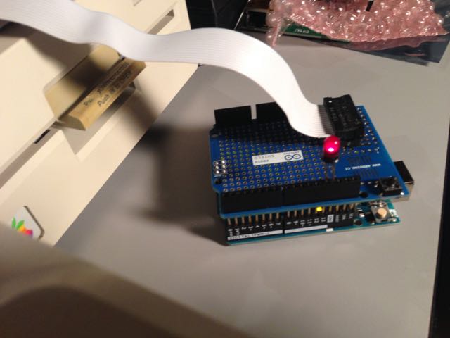
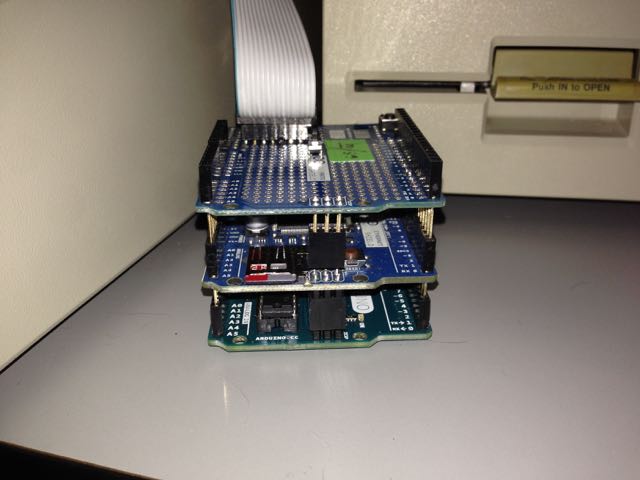
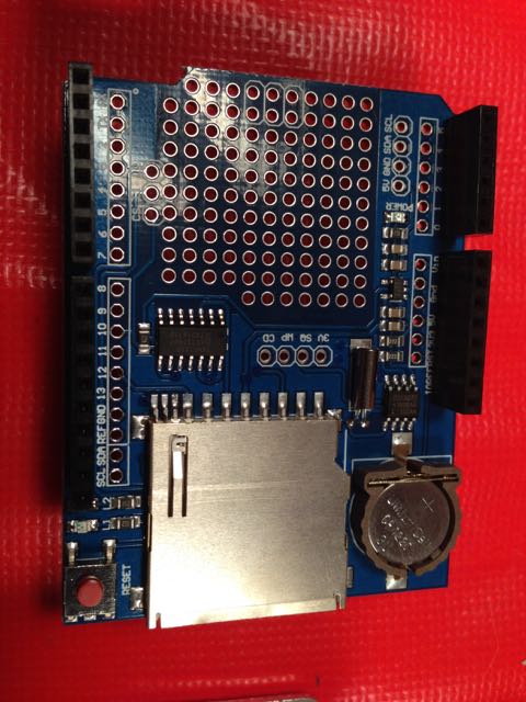
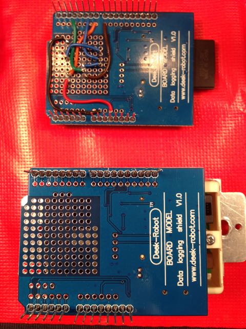
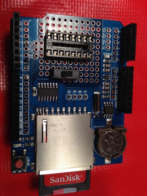
As a quick follow-up, I’ve received the cheap Chinese order from BangGood of the GeekCreit Uno and Data Logger Shield. Not nearly the quality of the original, but the price is right. Three knock-off Unos and Data Logger Shields cost less than one original Arduino Uno. The Data Logger Shield is a nice shield that has a full size SD card port and a Real Time Clock chip. Here it is being built up with a socket for the game port cable:

The Arduino/AppleSlave project has been updated to use the SlaveSelect pin on pin 10 and add the RTCLib from AdaFruit.
Also, note that you will need to download a USB serial port driver to use the Arduino IDE under Windows or OS X. So not quite plug and play. I’ve created a quick video showing off the new parts:
Feel free to leave feedback on the PLASMA GitHub site, or drop me a line.
Enjoy!