Having received a package in the mail last week containing Andrew and Ivan Hogan’s GamePort I/O Board, it got my creative juices flowing. The GamePort I/O Board is a great interface to big, external devices. It’s meant to control things like electronic sprinkler heads, relays, that sort of thing. I wrote a PLASMA sketch to simplify the game port interface, and generally had fun with it. But, as I sat there looking at the game port specification in the Apple II Reference Manual, I noted a utility strobe signal that would produce a 1/2 micro-second pulse when referenced. Hmm. In years past, I had tried building an SPI (Serial Interface Bus) connection using a 6522 and external shift register so I could adapt an Arduino Ethernet Shield to the Apple II. It almost worked, but not quite. And not too long ago, Charles Mangin of Option8 fame had brought up for discussion a method of talking to an Arduino over the Apple II’s game port, and a KansasFest presentation to match. All of this must have sunk into my sub conscience, because I actually had a dream about how to bit-bang an SPI interface from the Apple II to an Arduino over the game port.
Why SPI? Well, it is a nicely defined protocol that has some interesting properties. More information can be found on WikiPedia, but it boils down to having a master talking to a slave in a synchronous manner. Data travels both ways: a bit is read as one is written. So you read and write at the same time. Not all data need be relevant, however. SPI doesn’t define a high-level protocol, just a transfer mechanism. And it only requires 4 wires: SlaveSelect, Clock, MasterOut/SlaveIn, and MasterIn/SlaveOut.
The Apple II game port isn’t the greatest interface for implementing a fast bit-banged protocol, but it isn’t too bad, either. The master is responsible for the clock, which is where that utility strobe comes in. Along with the strobe, it has 4 general purpose digital outputs and 3 general purpose digital inputs. Programming the outputs is a little strange, and somewhat time consuming on a 6502 if you want to scan out a series of bits. For SPI, only two outputs are needed and one input, if the strobe is used as the clock. This is where the strobe signal really helps out with the bit-banging approach. The clock signal doesn’t have to be symmetrical, the slave just wants to see the edges, and it doesn’t have to adhere to a consistent rate (although I assume most hardware implementations are). So that takes care of the Apple II side of things. What about the Arduino?
SPI on the Arduino is officially only supported in master mode. If I was going to bit-bang the interface on the Apple II, why not the Arduino. One of my goals was to leave the hardware SPI interface on the Arduino intact so I could use the Arduino as a proxy for the Apple II when talking to the myriad of Arduino shields out there – many of which talk SPI. On top of that, there are some nice libraries that implement higher level interfaces such as TCP/IP and FAT file systems. Now the Arduino Uno (well, the ATmega 328P) has some nice features for interfacing to all sorts of things, and the Arduino IDE is a great prototyping environment, so it did’t take long to whip up a connection between the Apple II game port and the digital pins on the Uno. It did take a few iterations to identify the best way to interrupt the 328P when the Apple II was initiating a transaction. Software polling was going to be slow, and potentially miss the quick clock pulses. So I connected the clock signal to an interrupt to make sure I didn’t miss any. However, there was enough potential jitter in servicing the interrupt that bits could get lost. So I ended up interrupting on the assertion of SlaveSelect, and went into a tight loop watching the clock signal and updating the shift registers. Because of the tight constraints during data transmission, I skipped the Wiring library and went straight to the I/O ports on the 328P. By choosing my pins wisely, it made the software particularly simple to shift data in and out over the wires.
Testing out the wiring options was made easier by using a breadboard to connect the game port to the Arduino’s header.
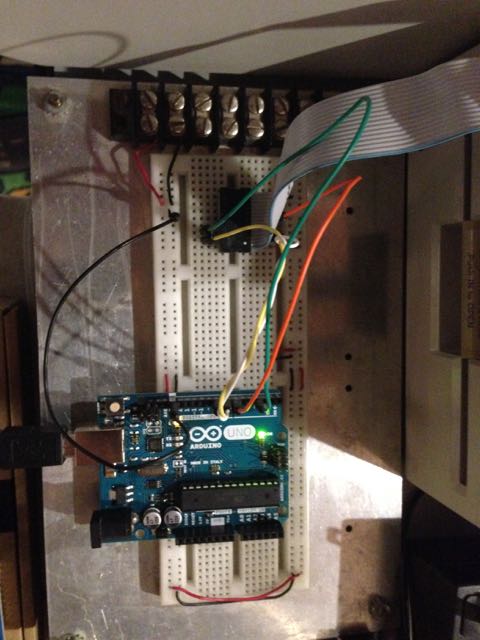 Switching the pins around was a matter of moving the wire.
Finally, I came to a conclusion as to the best wiring connections:
 Apple II        Signal         Arduino
 --------        ------         -------
   AN0            MOSI        Digital Pin 8
C040 Strobe       SCK         Digital Pin 6
   AN1             SS         Digital Pin 3
   PB0            MISO        Digital Pin 7
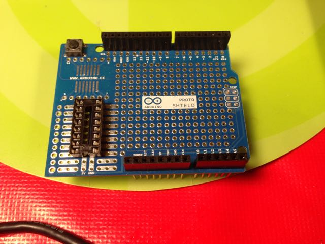
Once I was satisfied the interface was solid, I soldered up my one and only Arduino Proto Shield, which was waiting for just the perfect project to commit to.
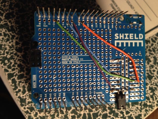
 I soldered the wires to the back to keep it nice and clean.
 The game port does have a 5V supply, but it is very limited in current: 100mA. A base Arduino without much load should be able to keep under that requirement, but when connected to a host PC for programming, I didn’t want my 5V supplies fighting each other, so I added a jumper for the game port’s 5V. The Arduino site says this isn’t recommended. Yeah, whatever. Finally, it all came together and I ran my test program on it.
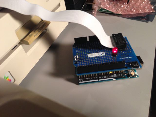 The LED lights up whenever a key is pressed on the keyboard that has the LSB set, or turns the LED off when it doesn’t. The Arduino’s on-board LED was somewhat covered up by the Proto Shield, so I plugged another one right into the header so you could see it. You can find the Arduino sketch and the PLASMA sketch on GitHub.
Going forward, I would like to leverage the FAT filesystem library for SD cards so I can read and write files to and from the Apple II directly from the card. That will greatly simplify my file transfer workflow.