Category Archives: Apple II

Apple II Pi Software – System Code

1.0 Introduction:

Apple II Pi is a combination of Apple II code, Linux code, and a serial port connection (either cable or optional plug-in card for the Apple IIe). It integrates the Apple II ProDOS world into the Raspbian Linux world of the Raspberry Pi, thus creating Apple II Pi.

The code repository is at GitHub. https://github.com/dschmenk/apple2pi

2.0 a2pid:

On the Linux side, the Apple II Pi daemon runs in the background, listening to the Apple II on a serial port connection, listening on TCP/IP port 6502 6551 (so as not to conflict with GSport on port 6502) for Linux client connections, and managing the insertion of Apple II keyboard and mouse events into the Linux input subsytem. It’s not something normally visisble, but is the traffic cop between the Apple II, Linux input events, and Linux client programs that interact with the Apple II.

2.1 Keyboard Mapping:

a2pid is responsible for mapping the ASCII characters from the Apple II keyboard into modern scancodes used by the Linux input subsystem. Because of the limited number of keys, the Open-Apple and Solid-Apple keys are used as modifiers to the other keys. Open-Apple is mapped to the ALT key. Solid-Apple is used as a FN modifier key: it alters the arrow keys to HOME, END, PGUP, and PGDN. It also converts the number ksys into F1-F10 equivalents. Solid-Apple+DELETE becomes DEL instead of BACKSPACE. Two special key sequences have a backdoor function for Apple II Pi.  Open-Apple+Solid-Apple+DELETE will exit the Apple II client code, returning keyboard control back to the Apple II. If you want to resume interaction with the Linux daemon, you can either press RESET, re-run the A2PI:STARTUP program, or reboot the A2PI floppy.

3.0 a2serclk:

a2serclk is the utility required when using the optional plug-in card for Apple II Pi. Otherwise, it isn’t needed.

3.0 a2serclk is deprecated – it has been integrated into a2pid.

4.0 A2PI.PO:

The ProDOS disk image file. Inside you will find ProDOS version 1.9, MERLIN8 version 2.59 assembler, BASIC.SYSTEM version 1.5, the STARTUP program that loads the A2PI device driver, and the CONFIG program to configure the slot connection to a2pid. A2PI.S is the source to the device driver developed using the MERLIN8 assembler. The device driver is loaded into the upper ProDOS BASIC buffer space so it won’t interfere with BASIC programs. However, leaving BASIC will disconnect the A2PI driver and keyboard/mouse operations won’t be seen in Linux until STARTUP is re-run from BASIC.

5.0 Conclusion:

The programs that make up the foundation of Apple II Pi should be hidden from sight and “just work”.

Apple II Pi Software – Utilities

1.0 Introduction:
This documents the utilities included in the Apple II Pi project. See the project README.md for installation instructions.

2.0 Contents:

Interactive tools

a2mon – Apple 1 like monitor
bintomon – Binary to monitor format converter
a2term – Apple II console

Development tools

bload – Load binary file
brun – Run binary file
a2lib.c – Simple a2pid connection library

Disk image tools

dskread – Read disk image
dskwrite – Write disk image

Supplemental files

a2slideshow.mon – Famous slideshow program in monitor format

a2slideshow.bin – Famous slideshow program binary

execfile – Sample exec file for a2term

Other files

a2pid – Apple II Pi Linux daemon

A2Pi.PO

3.0 Interactive Tools:

These tools are used to interact with the Apple II from the keyboard and screen. As real Linux tools, they can also accept I/O redirection to automate keyboard input and capture output. The other common ability (with the exception of bintomon) of the tools is to be able to connect to Apple II Pi remotely over the network. A final, optional argument is the IP address of the Apple II Pi computer. The tools can be built for a multitude of Linux and Unix computers and run remotely, connecting to the Apple II Pi.

3.1 a2mon:

The Apple 1 has a very simple monitor program that can examine and change memory, as well as execute code. a2mon is modeled after that monitor. As such, it isn’t very powerful, but can be a valuable tool when combined with I/O redirection. You can incorporate complete programs in the monitor format, or just change a few bytes of memory. Calling code in RAM or ROM is simple.

There is a concept of current address. To specify an address, just enter it first on the command line. To change memory contents, enter a colon either after a specific address or by it self to use the current address followed by the bytes separated by spaces. Reading a range of memory involves specifying two address separated by a period. To begin execution of code (run) at a specific address or current address, type ‘r’. Finally, ‘q’, will quit the session and return.

Run as:

a2mon [IP addr]

3.2 bintomon:


Converting a binary file to a monitor input format can be accomplished with bintomon. The command is run as:

bintomon  <filename> [IP addr]

standard output can be redirected to save the formatted text or piped into a2mon.

3.3 a2term:

Probably the most interesting of the tools, a2term connects the Linux console to the Apple II console. a2term connects to the Apple II running ProDOS BASIC. This is roughly equivalent to using an old serial terminal connected to a Super Serial Card and issuing commands to redirect the keyboard and screen I/O hooks.

AppleSoft programs, ProDOS commands, and Monitor commands are all available. Like a2mon, the input and output can be redirected to files for automated keyboard input and ouput capture. Similar to running the EXEC command from ProDOS (and DOS 3.3). To quit, use the ESC-Q sequence. To send an actual ESC character, press ESC twice. The DELETE key has been remapped to BACKSPACE for convenience.

There are some limitations that have to be followed. The screen editing/cursor movement keys are not available. As mentioned before, the DELETE key now backspaces to aid editing. Do NOT leave AppleSoft BASIC, or the mouse and keyboard will be disconnected from Apple II Pi and you will have to re-start BASIC.SYSTEM from the A2PI boot disk. If you run a program that doesn’t do any screen or keyboard I/O, you will see that your mouse and keyboard are no longer reponsive. Apple II Pi relies on the screen and keyboard I/O hooks to provide the co-operative tasking between Apple II programs and Pi input events. CTRL-C will usually break into an AppleSoft program (may take a few trys) but machine code that isn’t responding will require a press of RESET. Not to worry, Apple II Pi will resync and return to BASIC (assuming memory hasn’t been overwritten). In drastic cases, an Apple II reboot may be necessary. Apple II Pi will resync and you may continue on.

Run as:

a2term  [IP addr]

4.0 Development Tools:
Apple II Pi really shines as a development environment for the Apple II. To aid in the rapid development process, these tools were created to test binaries created in the Pi’s native environment on the actual Apple II.

4.1 bload:

bload will read a file from the Linux filesystem and copy it into the Apple II memory at the address specified. Apple II Pi incorporated a relatively fast communications channel so this operation is about as fast as reading from the floppy. Run as:

bload <filename> [IP addr]

Hexadecimal addresses are entered in ‘0x’ format otherwise decimal addresses are assumed.

4.2 brun:

Like bload, brun will load the binary file but will also jump to the loading address. Run as:

brun <filename> [IP addr]

4.3 a2lib.c:

All the tools include a2lib.c as a very poor, cheesy, horrible, etc. way to implement the Apple II Pi daemon API. Only useful if you are looking to write your own tool or modify the code of the existing tools.

5.0 Floppy Disk Image Tools:

Getting floppy disk image files to and from actual floppy drives has been greatly simplified with wonderful tools like ADTPro. For most sophisticated image transfer applications, use something like ADTPro. However, when something cheap, quick, and dirty will suffice, these two tools can make fast work of reading or writing disk images. Both of these tools only work on a 5 1/4 floppy  in drive 1 of slot 6. The only image format they support is the ProDOS order: .PO

5.1 dskread:

dskread will read the disk in the floppy drive and create a disk image using the volume name on the floppy for the filename. If the disk volume is HELLO, HELLO.PO is the name of the resulting disk image file. Run as:

dskread [IP addr]

5.2 dskwrite:

Simple, just like dskread. dskwrite is run as:

dskwrite <filename> [IP addr]

It will prompt you to overwrite the current volume name. ‘Y’ or ‘y’ will proceed and the floppy will be written.

6.0 Supplemtal Files:

Thes files are supplements to the tools to demonstrate their operation.

6.1 a2slideshow.mon:

Use with a2mon as:

a2mon < a2slideshow.mon

Press ESC to leave the slideshow. The slideshow is displayed on the Apple II screen, not the Pis’s screen.

6.2 a2slideshow.bin

Use with brun as:

brun a2slideshow.bin 0x2000

Press ESC to leave the slideshow. The slideshow is displayed on the Apple II screen, not the Pis’s screen.

6.3 execfile:

Use with a2term as:

a2term < execfile

Watch it automate AppleSoft.

7.0 Other Files:

These are the other files in the distribution.

7.1 a2serclk:

The Apple II Pi add-on card for the Apple IIe is a very minimal design that takes advantage of the built in General Purpose I/O (GPIO) pins of the Raspberry Pi. One of those pins is programmed by a2serclk to provide the clocking signal to the 6551 ACIA chip on the add-on card, thus saving a $2 crystal oscillator. Not needed if you are using an Apple //c or Super Serial Card in an Apple IIe to communicate to the Raspberry Pi.

7.2 a2pid:

The Linux daemon. See a2pid.txt.

7.3 A2PI.PO:

The Apple II client device driver and configuration utility.

8.0 Conclusion:

These tools are all very simple but adhere to the Unix principle of minimal funcionality with flexible I/O. They can be combined with shell scripts to create powerful commands. Feel free to add more.
Apple II + Raspberry Pi = Apple II Pi

One of the most interesting computers to come to market in the past year is the Raspberry Pi. Of the many uses I’ve come up with for this diminutive device is to treat it as an upgrade to my Apple II, or, thought of another way, the Apple II as a crazy cool case for the Raspberry Pi (RPi). Now, for the past 20 years, people have speculated what the next Apple II could look like. The last issue of Juiced.GS, the only remaining Apple II periodical, had an interesting article about the Apple II nx (next, unix, ???). Of course, everyone has their own idea of what the next Apple II should look like, but there are a few obvious traits:  at least 32 bit CPU (6502 derivative preferred), some sort of unix OS, up-to-date graphics, modern connectivity, programmer focussed. Kind of sounds like the RPi, huh? For those that don’t know, the RPi has an ARM processor (who’s designers used the 6502 as a source of inspiration), has a fairly powerful GPU with HDMI output (and composite output for us retro types), USB 2.0, SD card storage, and 512 MB of main memory on the Model B (256 MB on the Model A).

If the RPi was to work with the Apple II, what would the interface be?  The RPi has a 26 pin GPIO header capable of driving many types of serial and parallel protocols. There were some early discussions about how an RPi could interface to an Apple II bus and control the peripherals at a low level. There was never a satisfactory solution given the low number of I/O pins and the difficulty programming them in real-time from Linux. So I settled on a different approach – use the TTL serial port available on the RPi GPIO header as the communications channel between the RPi and Apple II. The Apple II becomes a co-processor, of sorts, to the RPi. An additional benefit of a serial interface is that the IIc can partake in the upgrade.  The Super Serial Card in the Apple IIe would be the first implementation of the serial interface followed by a dedicated prototype card that would accept the RPi and connect to an on-board serial chip.

A protocol was developed to allow the Apple II to communicate at 115K  baud without interrupts, sending keyboard and mouse events to the RPi.  The RPi can insert a request command to the Apple II, which will be followed by the Apple II enacting on the request in it’s event loop. Currently the RPi can request memory reads, memory writes, and calls.  A small assembly language program runs on the Apple II while a small daemon runs on the RPi.  Both talk to each other over the serial port; the Linux daemon inserts input events into the Linux input subsystem as well as having a socket interface to accept requests to pass on to the Apple II from external programs.

The software was developed on an Apple IIc with a serial cable connected to a TTL->RS232 converter on the RPi’s GPIO serial pins. Merlin 8 was used to develop the code locally on the Apple II while the Linux daemon was written in user mode C (no kernel modules). Neither program’s source code is particularly attractive, but they get the job done. You can find the source code and Apple II disk image on GitHub: https://github.com/dschmenk/apple2pi.  Note that this code isn’t really tied to the RPi.  It will actually work with any modern Linux distribution on an x86.

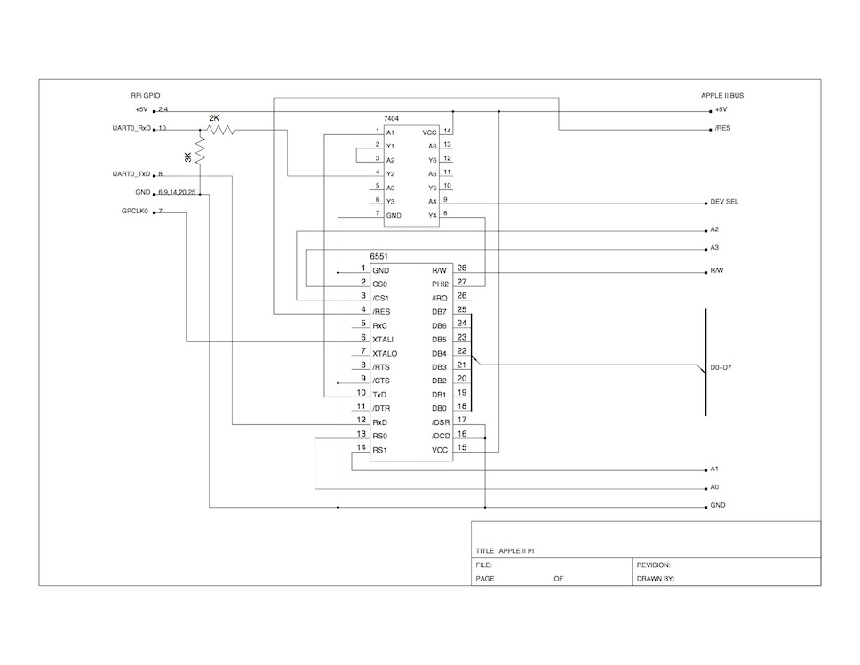
Apple II Pi will work just fine using off-the-shelf parts you can buy from eBay (or parts you already have).  However, if you want to take it to the next level and integrate your Raspberry Pi into your Apple IIe case for the ultimate upgrade, here is what you’ll need:

apple2pi schematic

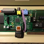
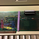
I used a ribbon cable to bring the GPIO header around to the prototype card so the RPi would be oriented in such a way that the ports would still be accessible with the case on.  Unfortunately, the RPi has ports on all side, so I sacrificed the composite video and analog audio access. Here are some pictures of my prototype board with a Model A Raspberry Pi:

Back of the board: 

Front of the board: 

There is one final software addition needed before the hardware will work.  In the source distribution is a program called a2serclk.  This will program the GPCLK pin to output the 1.8432 MHz clock signal needed for the 6551 baud rate generator.  Without this, the 6551 would require a physical crystal oscillator connected to the XTALI and XTALO pins.  Place a call to” /usr/local/bin/a2serclk” right before the call to “/usr/local/bin/a2pid –daemon” in the /etc/rc.local init script.

Here is a three part video series showing the development of the project:
Part 1
Part 2
Part 3
Part 4

QuickCam and the Apple II, Part II

Click here for Part I

Part II – The Software

The software turns out to be a bit easier once all the hardware is built.  The two main routines required are the read and write routines.  Writing a data byte to the QC involves writing the data to the output port then reading back the echo of the data from the QC to ensure it was received. Reading a data byte from QC involves bringing PCAck (Strobe) high, waiting for the QC to respond with CamRDY high, then reading the first nybble on the input data port.  Once the nybble has been read, deassert PCAck (Strobe), wait for CamRDY to go low, then read the second nybble from the input data port.  Because of the way the PC parallel port works, Nybble3 from the QC went through an inverter so the QC actually compliments Nybble3 so the PC would read the correct value right from the I/O port.  However, the APIC isn’t mapped like the PC parallel port, so this bit will show up inverted on the input data port.  The 6502 has to compliment Nybble3 to get the correct value.  One other issue mentioned in the hardware post has to be dealt with – the Output Strobe.  On the APIC, the Output Strobe connected to PCAck, has an automatic pulse duration that can be set with switches on the card. Because the actual duration of this pulse is dynamic, handshaking with the CamRDY signal, a way to keep re-triggering this signal so it doesn’t prematurely deactivate has to be developed.  As luck would have it, the maximum strobe pulse is 15 us, just long enough to check the status of PCAck and either re-trigger the strobe or read the data on the input port before the strobe de-asserts. Finally, reading the echo from a data write is the exact same code as reading a data byte, the two are combined and the data write routine falls right into the data read.  Here are the two most important routines with the slot*16 in the X register:

QCWRITE STA $C080,X  ; DATA OUT -> CMD
QCREAD  STA $C082,X  ; STROBE -> PCACK
        LSR $C084,X  ; ACK (BIT 0) <- CAMRDY
        BCC QCREAD
        LDA $C083,X  ; DATA IN <- HI NYBBLE
        AND #$F0     ; DO ENOUGH WORK SO HANDSHAKE CAN BE SKIPPED
        EOR #$88     ; COMPLIMENT NYBBLE3
        STA TMP
        LDA #$0F
        AND $C083,X  ; DATA IN <- LO NYBBLE
        EOR TMP      ; COMBINE LO AND HI NYBBLES
        RTS

This is the core of the code to read and write the QC.  The other important routine is the reset/init routine.  The original B/W QC would return a parameter to the GetVersion command of 0.  The later Color QC returned a non-zero value, plus an additional value.  Care must be taken to take this into account if code is to work on both.  Also, this code isn’t smart – if a QC isn’t attached, it will wait forever.

RESET   LDA #$FF
        STA $C085,X ; RESET QC
        JSR $FCA8   ; WAIT
        LDA #$17    ; GET_VER
        JSR QCWRITE
        CMP #$17    ; GOOD ECHO?
        BNE QCERR
        JSR QCREAD
        BEQ QCBW
        PHA
        JSR QCREAD ; COLOR QC HAS 2 PARMS
        PLA
QCBW    RTS

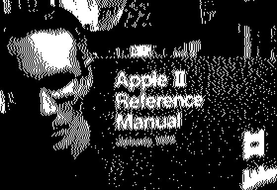
Once we can initialize the QC and read and write commands, time to read video frame data.  The QC can return pixel data in either 4BPP or 6BPP mode.  Due to the limitations of the Apple II graphics, 4BPP seems adequate so I don’t bother with 6BPP.  I wrote a very simple program to grab small video frames and put them on the Apple’s low resolution graphics screen.  By mapping the color blocks into a corresponding grey scale ramp and displaying the result on a monochrome monitor, live video that roughly resembles what the QC is looking at results.  I added controls to adjust the exposure value and contrast to that the best image can be obtained given the severe constraints of 4 bit pixels and a 40×48 graphics mode.  Finally, I added a high resolution capture command that would take a video frame and display it on the high res screen.  Now the high res screen only shows 1 bit pixels, so I had to employ a primitive error diffusion algorithm to get a respectable image.  I’ll let you be the judge of the results:

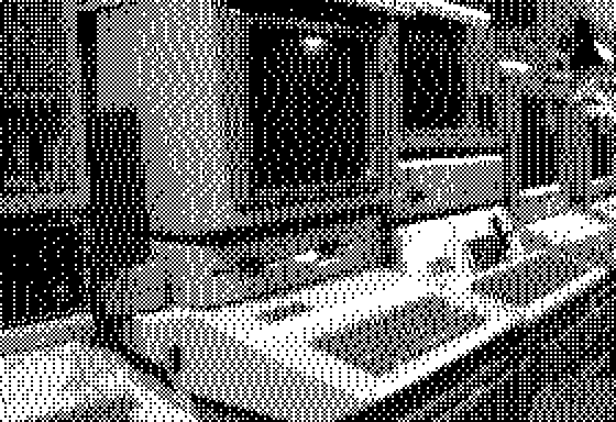
I added a small ordered dither to the pixel calculations to bring out the mid and low grey values.  Here is an image of some of my collection:

Finally, here is the code for the lo-res video/hi-res frame capture.  It isn’t really well documented, but is fairly short and simple.  Meant to be assembled by EDASM.

        ORG     $2000
DATAOUT EQU     $C080
STROBE  EQU     $C082
DATAIN  EQU     $C083
ACK     EQU     $C084
RESET   EQU     $C085
WAIT    EQU     $FCA8
ERR     EQU     $03
TMP     EQU     $06
HPIX    EQU     $06
LASTERR EQU     $07
*
* HARD-CODE SLOT 1 AND RESET
*
        LDX     #$10
        JSR     QCRESET
        BCC     GR
        RTS
*
* SET LORES GRAPHICS
*
GR      LDA     $C050
        LDA     $C056
        LDA     $C052
        LDA     $C054
*
* SET FRAME DIMENSIONS
*
        LDX     #$10
        LDA     #45
        JSR     QCLEFT
        LDA     #25
        JSR     QCTOP
        LDA     #20
        JSR     QCNUMH
        LDA     #48
        JSR     QCNUMV
*
* SET FRAME CONTRAST/EXPOSURE
*
SETCONT LDA     CONT
        JSR     QCCONT
SETEXP  LDA     EXP
        JSR     QCEXP
*
* GRAB FRAME INTO LORES GRAPHICS SCREEN
*
VIDEO   LDA     #$08
        JSR     QCFRAME
        LDA     #$00
        STA     LINE
*
* EVEN LINES
*
ELINE   JSR     $F847   ; GBASECALC
        LDY     #$00
EPIX    STA     STROBE,X
        LSR     ACK,X
        BCC     EPIX
        LDA     DATAIN,X
        AND     #$0F
        TAX
        LDA     GREYLO,X
        LDX     #$10
        STA     ($26),Y
        INY
        LDA     DATAIN,X
        AND     #$0F
        TAX
        LDA     GREYLO,X
        LDX     #$10
        STA     ($26),Y
        INY
        CPY     #40
        BNE     EPIX
*
* ODD LINES
*
OLINE   LDY     #$00
OPIX    STA     STROBE,X
        LSR     ACK,X
        BCC     OPIX
        LDA     DATAIN,X
        AND     #$0F
        TAX
        LDA     GREYHI,X
        LDX     #$10
        ORA     ($26),Y
        STA     ($26),Y
        INY
        LDA     DATAIN,X
        AND     #$0F
        TAX
        LDA     GREYHI,X
        LDX     #$10
        ORA     ($26),Y
        STA     ($26),Y
        INY
        CPY     #40
        BNE     OPIX
        INC     LINE
        LDA     LINE
        CMP     #24
        BEQ     EOFRM
        JMP     ELINE
EOFRM   JSR     QCEOF
*
* CHEK FOR KEYPRESS
*
        LDA     $C000
        BMI     KEYPRESS
        JMP     VIDEO
KEYPRESS STA    $C010
        CMP     #$D1    ; Q
        BEQ     DONE
        CMP     #$AB    ; +
        BNE     KP1
        INC     EXP
        JMP     SETEXP
KP1     CMP     #$AD    ; -
        BNE     KP2
        DEC     EXP
        JMP     SETEXP
KP2     CMP     #$BC    ; <
        BNE     KP3
        DEC     CONT
        JMP     SETCONT
KP3     CMP     #$BE    ; >
        BNE     KPEND
        INC     CONT
        JMP     SETCONT
KPEND   CMP     #$A0    ; SPACEBAR
        BEQ     HRCAP
        JMP     VIDEO
DONE    JMP     $FB39   ; TEXT
*
* HIRES FRAME CAPTURE
*
HRCAP   LDA     $C057
        LDA     $C055
        LDA     #20
        JSR     QCLEFT
        LDA     #25
        JSR     QCTOP
        LDA     #140
        JSR     QCNUMH
        LDA     #192
        JSR     QCNUMV
        LDA     #$00
        JSR     QCFRAME
        LDA     #$40
        STA     $E6
        STA     $27
        LDY     #$00
        STY     $26
        STY     LINE
        STY     LASTERR
*
* FIRST SEVEN BITS OF HIRES WORD - EVEN LINES
*
EHLINE  JSR     QCPIXHI
        CLC
        ADC     #4
        JSR     PIXTST
        JSR     QCPIXLO
        SEC
        SBC     #1
        JSR     PIXTST
        JSR     QCPIXHI
        CLC
        ADC     #4
        JSR     PIXTST
        JSR     QCPIXLO
        SEC
        SBC     #1
        JSR     PIXTST
        JSR     QCPIXHI
        CLC
        ADC     #4
        JSR     PIXTST
        JSR     QCPIXLO
        SEC
        SBC     #1
        JSR     PIXTST
        JSR     QCPIXHI
        CLC
        ADC     #4
        JSR     PIXTST
        LDA     HPIX
        LSR
        STA     ($26),Y
        INY
*
* SECOND BYTE OF HIRES WORD
*
        JSR     QCPIXLO
        SEC
        SBC     #1
        JSR     PIXTST
        JSR     QCPIXHI
        CLC
        ADC     #4
        JSR     PIXTST
        JSR     QCPIXLO
        SEC
        SBC     #1
        JSR     PIXTST
        JSR     QCPIXHI
        CLC
        ADC     #4
        JSR     PIXTST
        JSR     QCPIXLO
        SEC
        SBC     #1
        JSR     PIXTST
        JSR     QCPIXHI
        CLC
        ADC     #4
        JSR     PIXTST
        JSR     QCPIXLO
        SEC
        SBC     #1
        JSR     PIXTST
        LDA     HPIX
        LSR
        STA     ($26),Y
        INY
        CPY     #40
        BEQ     NEXTEHLINE
        JMP     EHLINE
NEXTEHLINE JSR  $F504   ; INC HPOSN
        INC     LINE
        LDY     #$00
*
* FIRST SEVEN BITS OF HIRES WORD - ODD LINES
*
OHLINE  JSR     QCPIXHI
        SEC
        SBC     #4
        JSR     PIXTST
        JSR     QCPIXLO
        CLC
        ADC     #1
        JSR     PIXTST
        JSR     QCPIXHI
        SEC
        SBC     #4
        JSR     PIXTST
        JSR     QCPIXLO
        CLC
        ADC     #1
        JSR     PIXTST
        JSR     QCPIXHI
        SEC
        SBC     #4
        JSR     PIXTST
        JSR     QCPIXLO
        CLC
        ADC     #1
        JSR     PIXTST
        JSR     QCPIXHI
        SEC
        SBC     #4
        JSR     PIXTST
        LDA     HPIX
        LSR
        STA     ($26),Y
        INY
*
* SECOND BYTE OF HIRES WORD
*
        JSR     QCPIXLO
        CLC
        ADC     #1
        JSR     PIXTST
        JSR     QCPIXHI
        SEC
        SBC     #4
        JSR     PIXTST
        JSR     QCPIXLO
        CLC
        ADC     #1
        JSR     PIXTST
        JSR     QCPIXHI
        SEC
        SBC     #4
        JSR     PIXTST
        JSR     QCPIXLO
        CLC
        ADC     #1
        JSR     PIXTST
        JSR     QCPIXHI
        SEC
        SBC     #4
        JSR     PIXTST
        JSR     QCPIXLO
        CLC
        ADC     #1
        JSR     PIXTST
        LDA     HPIX
        LSR
        STA     ($26),Y
        INY
        CPY     #40
        BEQ     NEXTOHLINE
        JMP     OHLINE
NEXTOHLINE JSR  $F504   ; INC HPOSN
        INC     LINE
        LDA     LINE
        CMP     #192
        BEQ     EXIT
        LDY     #$00
        JMP     EHLINE
EXIT    JMP     QCEOF
*
* SIMPLE ERROR DIFFUSION
*
PIXTST  CLC
        ADC     LASTERR
        CMP     #$08
        BMI     PIXNEG
        ROR     HPIX
        SEC
        SBC     #$0F
        CMP     #$80
        ROR
        STA     LASTERR
        RTS
PIXNEG  LSR     HPIX
        CMP     #$80
        ROR
        STA     LASTERR
        RTS
EXP     DB      96
CONT    DB      104
LINE    DB      $00
*
* QCAM PIXEL DATA -> LORES GREYSCALE
*
GREYHI  DB      $30,$60,$A0,$50,$40,$80,$20,$10
        DB      $00,$F0,$E0,$D0,$70,$B0,$90,$C0
GREYLO  DB      $03,$06,$0A,$05,$04,$08,$02,$01
        DB      $00,$0F,$0E,$0D,$07,$0B,$09,$0C
***************************
*
*    QUICKCAM ROUTINES
*
***************************
*
* RESET QUICKCAM
*
QCRESET STA     RESET,X
        STX     TMP
        LDA     #$FF
        JSR     WAIT
        LDX     TMP
        LDA     #$17    ; GET VERSION
        JSR     QCWRITE
        CMP     #$17
        BEQ     QCOK
        SEC
        RTS
QCOK    JSR     QCREAD
        BEQ     QCBW
        PHA
        JSR     QCREAD
        PLA
QCBW    LDA     #$19    ; SET CONTRAST
        JSR     QCWRITE
        LDA     #104
        JSR     QCWRITE
        LDA     #$1B    ; AUTO CALIBRATE
        JSR     QCWRITE
        JSR     QCWRITE ; DUMMY PARAMETER
QCCAL   LDA     #$7F
        JSR     WAIT
        LDA     #$21    ; GET OFFSET
        JSR     QCWRITE
        JSR     QCREAD
        CMP     #$FF
        BEQ     QCCAL
        CLC
        RTS
*
* SET CONTRAST IN ACCUM
*
QCCONT  PHA
        LDA     #$19    ; SET CONTRAST
        JSR     QCWRITE
        PLA
        JMP     QCWRITE
*
* SET EXPOSURE IN ACCUM
*
QCEXP   PHA
        LDA     #$0B    ; SET EXPOSURE
        JSR     QCWRITE
        PLA
        JMP     QCWRITE
*
* SET TOP OF FRAME
*
QCTOP   PHA
        LDA     #$0D
        JSR     QCWRITE
        PLA
        JMP     QCWRITE
*
* SET FRAME LEFT COORDINATE
*
QCLEFT  PHA
        LDA     #$0F
        JSR     QCWRITE
        PLA
        JMP     QCWRITE
*
* SET FRAME LINES TO TRANSFER
*
QCNUMV PHA
        LDA     #$11
        JSR     QCWRITE
        PLA
        JMP     QCWRITE
*
* SET FRAME PIXELS PER LINE
*
QCNUMH  PHA
        LDA     #$13
        JSR     QCWRITE
        PLA
        JMP     QCWRITE
*
* COMPLETE END OF FRAME
*
QCEOF   STA     STROBE,X
        RTS
*
* SEND VIDEO FRAME
*
QCFRAME PHA
        LDA     #$07
        JSR     QCWRITE
        PLA
*
* WRITE BYTE TO CAM, FALL THRU TO READ ECHO
*
QCWRITE STA     DATAOUT,X
*
* READ BYTE FROM CAM
*
QCREAD  STA     STROBE,X
        LSR     ACK,X
        BCC     QCREAD
        LDA     DATAIN,X
        AND     #$F0
        EOR     #$88
        STA     TMP
        LDA     #$0F
        AND     DATAIN,X
        EOR     TMP
        RTS
*
* READ HI NYBBLE FROM CAM
* - NYBBLE IS DUPLICATED IN HI & LO NYBBLE
*
QCREADHI STA    STROBE,X
        LSR     ACK,X
        BCC     QCREADHI
*
* READ LO NYBBLE FROM CAM
* - SAME AS HI NYBBLE W/O WAIT
*
QCREADLO LDA    DATAIN,X
        EOR     #$88
        RTS
*
* READ 4BPP AS B/W RAMP 0->F
*
QCPIXHI STA     STROBE,X
        LSR     ACK,X
        BCC     QCPIXHI
QCPIXLO LDA     DATAIN,X
        EOR     #$07
        CLC
        ADC     #$01
        AND     #$0F
        RTS

QuickCam and the Apple II

Part I – The Hardware

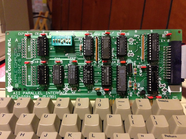
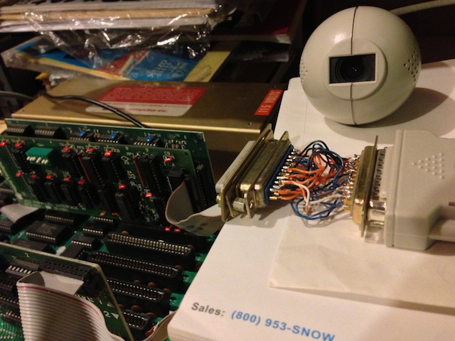
I finally got around to looking into connecting an old Connectix Greyscale QuickCam (QC) to an Apple II by way of the Apple Parallel Interface Card (APIC).  I had a couple of QuickCams lying around from my webcam astronomy days and bought some APICs off the ePay in anticipation of hooking them together someday.  I chose the APIC because it was the only parallel interface card I could find that implemented a full 8-bit input port.

Someday finally came.  I pulled out the programming specs on the QC and the APIC Installation and Operation Manual and went about figuring out the details of mapping the PC parallel port pinouts of the QC to the APIC.  This is the cable magic required to connect them together:

APIC Signal/Pin        QuickCam Signal/Pin
Strobe    15           PCAck     17
Ack       16           CamRDY    15
Input D7  18           Nybble3   11
Input D6  21           Nybble2   10
Input D5  19           Nybble1   12
Input D4  14           Nybble0   13
Input D3  25           Nybble3   11
Input D2   3           Nybble2   10
Input D1  17           Nybble1   12
Input D0   1           Nybble0   13
Output D7 13           Cmd7       9
Output D6 12           Cmd6       8
Output D5 11           Cmd5       7
Output D4 23           Cmd4       6
Output D3 22           Cmd3       5
Output D2  8           Cmd2       4
Output D1  6           Cmd1       3
Output D0  5           Cmd0       2
Aux Strobe 7           *Reset    16
GND       24,20,4,2    GND       18-25

There are a few things to take note of.  First, the output from the QC, Nybble3-0 is mapped to both to the most significant and the least significant nybble of the APICs 8 bit input port.  Since there are only enough I/O pins to implement the 4 bit communications protocol, I decided to map the one QC nybble to a full byte of input to the APIC.  The 6502 isn’t very good at shifting, so this alleviates the need to shift the nybble around for certain algorithms.  The second thing to note is the output strobe of the APIC connected to the PCAck of the QC.  This is one of the major handshake lines that works in conjunction with the CamRDY line for transferring data.  The host needs to hold this line high until the QC signals data is ready by raising CamRDY.  However, the APICs strobe is pulsed for a short duration, automatically returning to its previous state based upon switch settings on the APIC.  The strobe duration can be set using the first three switches on the APIC, from 1 us to 15 us.  Luckily, by maxing out the strobe duration to 15 us gives the 6502 just enough time to check the PCAck from the QC and re-triggering the strobe if it isn’t ready, or reading the data input port if it is – all before the strobe falls.  The second nybble from the QC quickly follows the first, so there was no need to check the handshaking signals again if the 6502 did enough work in-between nybble reads.  The last fortuitous connection was the Aux Strobe to *Reset.  The Aux Strobe isn’t really documented in the APIC manual except for the block diagram.  It delivers a short pulse whenever a certain address is accessed, and just happens to be active low, matching the requirements for the *Reset on the QC.  The APIC allows for the selection of active high or low for the regular strobe signal, thus matching the QCs PCAck signal.  The switch settings required on the APIC are thus:

      APIC SWITCH BLOCK
 1   2   3   4   5   6   7
ON  ON  ON  OFF ON  OFF OFF

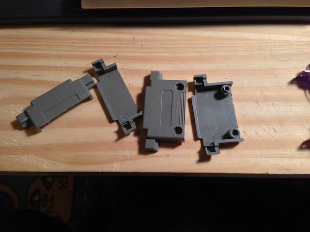
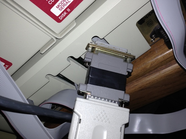
As this is a fairly delicate connection that I didn’t want to have to re-solder, I wanted to get a DB-25 dual ended hood to create a professional, reliable dongle.  However, those parts are no longer made, so I had to buy two DB-25 hoods and take a hack saw to them to create the piece I wanted.  Ultimately, I ended up with this:

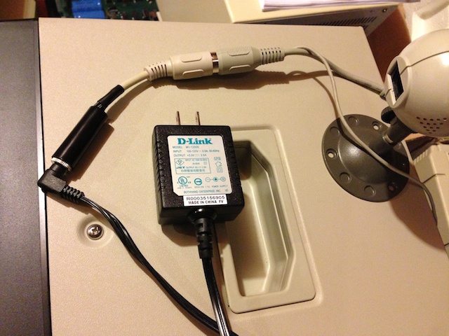
Finally, the QuickCam takes its power from the PS/2->AT keyboard connector since the parallel port doesn’t provide any.  I went through the parts bin, found an old +5V power adapter, an old keyboard cable to hack up, and along with a trip to Radio Shack for the power plug, created this:

The only lines required to connect are the +5V and ground.  Here is a link to a nice diagram showing which pins are power for the two connector types: http://www.bbdsoft.com/keyboard.html

Continue on to Connectix QuickCam and the Apple II, Part II – The Software